2-Watt Laser Satellite Comm: Why It Won’t Crush Starlink
Headlines are buzzing with claims that a newly tested 2-watt geostationary satellite laser link signals the end for Low Earth Orbit (LEO) mega-constellations. While the engineering required to shrink these optical transmitters is impressive, orbital physics cannot be ignored.
The real value of these small, high-efficiency systems lies in an entirely different direction. They serve to expand the data pipelines of isolated research platforms and military scouts, rather than replacing broad consumer internet networks.
A 2-watt laser satellite communication terminal uses a compact optical transmitter to beam data across space, often reaching speeds over 1 Gbps. While ideal for light payloads, its utility is bound by a fixed 240ms geostationary delay and atmospheric interference. It upgrades data backhauls rather than replacing low-latency consumer networks.
Key Takeaways
- Bandwidth is not latency: A 2W laser can hit gigabit speeds across vast distances, but geostationary placement locks in a permanent 240ms round-trip delay.
- SWaP efficiency gains: Advanced engineering allows 2W systems to weigh under 0.6 kilograms, making optical downlinks accessible to small CubeSats.
- Atmospheric bottlenecks: Keeping the signal stable through shifting air requires specialized ground-side light tracking rather than increasing satellite power.
- Severe thermal issues: Running a 2W laser inside a tiny satellite generates heavy localized heat that can warp structures and break optical alignment.
- Spectrum coordination relief: Optical links skip crowded radio frequency bands, avoiding complex international licensing delays.
Quick Answer for Payload Designers
If you are assessing a 2-watt laser payload for a small satellite project, focus on internal thermal paths and ground station infrastructure. The hardware safely solves data congestion for isolated instruments, but it requires highly precise tracking systems to stay locked onto its target.
The “2-Watt Laser vs. Starlink” Myth: Latency vs. Bandwidth
A laser beam traveling from geostationary orbit (GEO)—roughly 36,000 kilometers above Earth—faces an absolute physical boundary. No matter how clean or focused the 2-watt optical beam is, the trip down and back takes roughly a quarter of a second.
This inherent delay slows down real-time interactions. It makes the architecture non-viable for fast-twitch consumer applications like live gaming, high-frequency financial trading, or cellular backhauling.
By contrast, networks like Starlink operate in Low Earth Orbit (LEO) at heights around 550 kilometers. This much shorter distance keeps propagation delays down to single-digit milliseconds.
Common Mistake: Engineers sometimes focus purely on the raw data speed (gigabits per second) while ignoring the physical time it takes for the first packet of data to cross the orbital gulf. High bandwidth does not mean low latency.
Confirmed vs. Unconfirmed: The GEO Laser Breakthrough Exposed
| Capability / Metric | Confirmed Fact | Unconfirmed / Misleading Claim |
| Data Throughput | 1 Gbps transmission is fully achievable over 36,000 km using a 2W transmitter. | It provides faster real-time user browsing than low-orbit constellations. |
| Signal Latency | Speed of light demands a fixed ~240ms round-trip propagation delay from GEO. | It beats LEO networks on ping rates and real-time responsiveness. |
| Spectrum Access | Free-space optical links bypass all radio spectrum licensing constraints. | The optical beam is entirely immune to all forms of thick cloud blockage. |
| Payload Scale | Complete laser terminals can now integrate seamlessly into sub-6kg SmallSats. | The miniaturized design eliminates the need for large ground-station trackers. |
Inside the Hardware: Miniaturized Space Amplifiers (SWaP-C)
Squeezing a functional laser communications terminal into a modern SmallSat requires a radical reduction in Size, Weight, Power, and Cost (SWaP-C). Traditional satellite transmitters rely on heavy microwave dishes and massive power banks. Modern 2-watt systems compress this entire assembly into a package smaller than a shoebox.
The Four Stages of Optical Signal Generation
Building a high-rate optical link inside a constrained satellite chassis requires four sequential steps:
- The Seed Laser Source: Generates the base optical carrier signal, typically operating at the highly efficient 1064 nm or 1550 nm wavelengths.
- Preamplification Stage: Utilizes a Low-Noise Amplifier (LNA) to lift the weak raw signal clear of the systemic electronic noise floor.
- High-Power Fiber Amplification: Passes the signal through an Erbium-Doped Fiber Amplifier (EDFA) or Ytterbium (Yb) matrix, pumping it up to a steady 2-watt output.
- Collimating Optics & Steering: Directs the raw 2W output into a tightly focused parallel beam via Fast-Steering Mirrors (FSMs) for precise delivery.
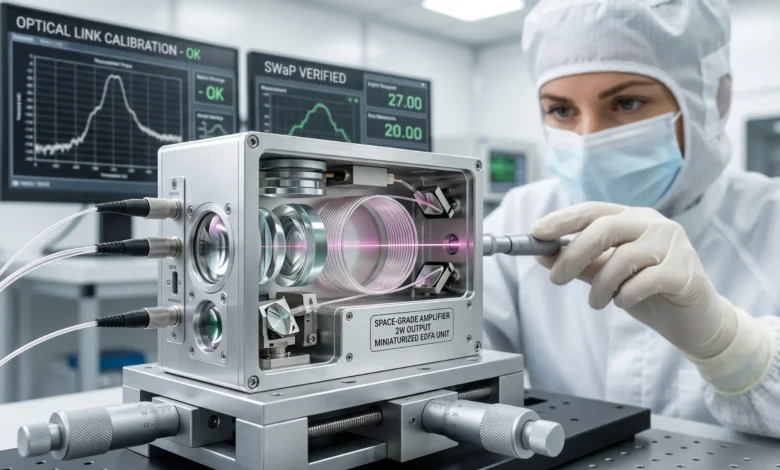
Case Study: The NICT CubeSOTA EDFA Assembly
A clear example of this hardware reduction comes from the National Institute of Information and Communications Technology (NICT) in Japan. For its CubeSOTA mission, the agency developed a miniaturized, space-grade 2-Watt EDFA.
This specific design successfully combines both the high-power amplifier and the low-noise amplifier into a single 0.56-kilogram block. The whole unit measures just 9 × 9.5 × 3.6 centimeters, proving that deep-space capable amplification can operate within standard CubeSat spatial limits. Engineers looking for structural baselines can verify similar form factor layouts through the SPIE Digital Library optical hardware index.
Technical Architecture Summary Box
SWaP Boundary Check: Squeezing a high-power optical amplifier into a small spacecraft frame requires shifting structural complexity from the sky to the ground. When your transmitter is limited to a strict 2-watt power window, link availability depends entirely on the sensitivity of your ground-side receiver and its ability to rebuild a distorted signal.
The Critical Engineering Challenge: Thermal Distortion and Alignment
While scaling down a laser transmitter solves payload weight limits, it introduces a severe environmental hazard: localized heat buildup. A continuous 2-watt optical output housed inside a tiny 3U CubeSat structure generates significant thermal friction at the amplifier node.
In the vacuum of space, there is no air to carry this heat away. Without dedicated internal thermal pathways, the surrounding aluminum chassis absorbs the heat directly, causing the structure to expand unevenly.
“Optical alignment errors can be induced by temperature variations, requiring precise tracking systems like Fast-Steering Mirrors.” (Optica Publishing Group, 2001)
Mini Case Study: The Thermal Misalignment Risk
Consider a typical CubeSat integration scenario. The High-Power Amplifier (HPA) within the EDFA runs hot during a long data downlink. Because the internal optics are mounted on a rigid bench, even a microscopic structural deformation—measured in micro-radians—shifts the angle of the transmitter.
This tiny warp throws the Fast-Steering Mirrors completely out of alignment. The laser beam drifts off target, instantly severing the free-space optical link with the ground station.
The Hardware Fix: To counteract satellite platform jitter and thermal shifting, engineers pair 2W transmitters with ultra-low expansion glass ceramic benches and highly sensitive tracking sensors. Modern terminals rely heavily on InGaAs quad cells and Avalanche Photodiodes (APDs). These sensors detect micro-shifts in the optical beam path and instantly tell the Fast-Steering Mirrors to adjust, keeping the link locked.
Mid-Article Summary: The Thermal Link Bottleneck
- Heat traps in a vacuum: Space offers no air convection, forcing small satellites to absorb the localized heat generated by a continuous 2-watt optical transmitter.
- Micro-radian failure: Minor thermal expansion in the chassis warps the internal optical bench, shifting the Fast-Steering Mirrors off target.
- Sensor correction: Maintaining a stable beam requires closed-loop tracking using InGaAs quad cells or APDs to correct thermal alignment drift in real time.
Overcoming the Atmosphere: Mode Diversity Reception
Once a 2-watt beam safely leaves the satellite, it faces its final barrier: Earth’s atmosphere. Firing a laser from thousands of kilometers away means the light must travel through miles of turbulent, shifting air.
By the time the beam reaches the ground station, it no longer looks like a clean, focused point of light. The atmosphere distorts the wavefront, scattering the signal into a shimmering, broken pattern. Standard Adaptive Optics (AO) systems—which physically bend mirrors to correct light—often fail when this turbulence becomes too heavy.
“The breakthrough was the receiver’s ability to salvage a signal the atmosphere had already punished… shifting the hard work to the ground.” (Daily Galaxy, 2026)
Instead of pushing more transmitter power from the satellite, modern ground stations rely on Mode Diversity Reception (MDR). This technique accepts that the light will arrive distorted. It uses a multi-plane light converter to split the broken signal into separate spatial channels. The system then digitally combines the strongest, clearest fragments into one steady data stream.
In recent high-altitude tests, applying MDR allowed operators to jump from a struggling 72% signal capture rate to a highly stable 91.1% usable signal. This ground-side processing is exactly what enables a relatively weak 2W space laser to maintain a reliable 1 Gbps link Optica Publishing Group database
Summary & Structural Design Directives
Miniaturized 2-watt laser satellite communication terminals represent a phenomenal leap forward for low-mass satellite downlinks and inter-satellite crosslinks. By fitting a high-power optical amplifier into a half-kilogram package, engineers have opened up gigabit data rates for the smallest spacecraft. However, these systems operate within strict physical boundaries governed by speed-of-light latency delays and dense internal thermal tolerances.
Next Steps for Payload Integrators:
- Conduct rigorous thermal vacuum (TVAC) simulation cycles to verify Fast-Steering Mirror orientation stability under steady 2W transmitter operation.
- Assess ground-station alignment options, confirming compatibility with multi-plane light conversion and Mode Diversity Reception architectures.
- Benchmark the 2W terminal’s electrical-to-optical conversion efficiency against the spacecraft’s overall baseline power generation limits.
FAQs
What is a 2-watt laser satellite communication terminal?
It is a miniaturized space payload, often utilizing an Erbium-Doped Fiber Amplifier (EDFA), designed to transmit data using light instead of radio waves. It operates at a 2-watt power output to balance high data transmission rates with the strict size and weight constraints of small satellites.
Can a 2-watt laser link replace Starlink?
No. While a 2-watt laser can transmit data at very high speeds (like 1 Gbps) from geostationary orbit, the physical distance creates a permanent ~240ms latency delay. Starlink operates in Low Earth Orbit (LEO), which offers the low single-digit millisecond latency required for real-time applications.
What wavelength do space laser communication terminals use?
Most modern space-grade optical terminals operate using near-infrared wavelengths, specifically the 1064 nm and 1550 nm bands. These wavelengths offer high efficiency and are supported by advanced fiber amplifier technology.
How fast can data transmit over a 2W space laser link?
When paired with advanced ground-station tracking and atmospheric correction technologies, a 2W transmitter can reliably push data downlinks exceeding 1 Gbps (Gigabit per second) over massive orbital distances.
What is the size and weight of a 2W laser communication terminal?
Recent miniaturization efforts have reduced these systems drastically. For example, the space-grade EDFA developed for the CubeSOTA mission weighs just 0.56 kilograms and measures 9 × 9.5 × 3.6 centimeters.
How does weather affect satellite laser communication?
Free-space optical links are highly sensitive to thick cloud cover and atmospheric turbulence. To maintain connections during poor weather, operators rely on ground-station diversity (placing multiple receivers in different climate zones) and advanced digital signal reconstruction.
What is an EDFA in space communications?
EDFA stands for Erbium-Doped Fiber Amplifier. It is an internal hardware component that boosts a weak optical signal into a high-power output (like 2 watts) without needing to convert the light back into an electrical signal first.
Why is thermal management critical for CubeSat laser terminals?
A continuous 2-watt laser generates significant localized heat. Without proper thermal dissipation, the satellite’s internal structure can warp slightly. Even a microscopic shift will misalign the optical tracking mirrors, breaking the data link with Earth.
References
- SPIE Digital Library, 2025
- Frontiers in Physics, 2025
- MDPI Electronics, 2022
- Utah State University (USU) Digital Commons, 2019
- Optica Publishing Group, 2001